
In the Istio system, in order to ensure the unity of policy coordination and experience, users will consider using Istio’s own Ingressgateway as the entrance to north-south traffic. Ingressgateway is generally deployed by deployment of multiple pods, scattered on multiple nodes of the cluster, depending on Due to the specific exposure type, especially in on-prem deployment, it is still necessary to deploy relevant load balancers outside the k8s cluster to load balance these ingressgateways, on the one hand, it can avoid access difficulties and operation and maintenance difficulties caused by multiple entrances. On the other hand, the high-performance and high-reliability F5 BIGIP can provide more function control and security value-added services for k8s cluster entrance traffic, which is similar to the Ingress controller.
Unlike exposing ordinary service svc to external BIG-IP, ingressgateway itself is a collection point of various service ports. It may itself listen to many ports, so it is not easy to treat ingressgateway as a single ordinary svc. This article mainly explains how to combine Istio ingressgateway with BIG-IP to enhance the entrance business capability.
The possible methods on the network structure are:
External load balancer — access to –> ingressgateway’s nodeport port
External load balancer — access to –> ingressgateway direct endpoints port (direct to pod)
From the point of view of performance, it is naturally the second direct pod method mentioned above that has better performance, depending on the network model of the k8s cluster. If the external and pod can be directly routed or the two-layer direct connection is naturally the easiest, if it cannot be directly routed, it needs to be based on vxlan and other tunnels to achieve pod direct. F5 BIGIP supports Layer 2 direct, dynamic routing or vxlan tunnel mode. Refer to this article for detailed network deployment structure , or search for related articles in this blog. In the following, we assume that F5 BIGIP has implemented vxlan with k8s cluster, which can reach the pod directly. The final data path is as follows:
client–>F5BIGIP–>Istio ingressgateway pod–>endpoints
The underlying implementation of Istio Ingressgateway is envoy. When we publish a service to Ingressgateway through Gateway+VirtualService resource, Ingressgateway will listen to the port specified in Gateway. Therefore, once a new service is released, there may be a new listening port. However, when we deploy the ingressgateway pod, we will not configure all the external mappings in advance. That is to say, the port that the container in the pod listens to is not configured in the deployment of the pod. Don’t worry, it can be directly accessed at this time. This listening port on the pod, although the deployment port is not specified in advance.
So how to load balance for Ingressgateway through BIGIP and dynamically discover these new monitoring services? The answer is naturally the solution described in this article. F5 BIGIP provides a controller that runs inside k8s and automatically pushes these changes to BIGIP. on. Since the same k8s svc contains one more port, you need to pay attention to the servicePort parameter when publishing this k8s svc to F5. The specific publishing process refers to the following steps:
Deploy Istio Gateway+VirtualService resources
Edit the k8s svc corresponding to the existing Ingressgateway and add new port and target port configurations
Configure a new F5 configmap resource and specify the corresponding servicePort to publish the new service
DEMO:
- First check the existing Ingressgateway pod ports are as follows, port 32400 is not exposed in the container port
        name: istio-proxy
        ports:
        - containerPort: 15020
          protocol: TCP
        - containerPort: 8080
          protocol: TCP
        - containerPort: 8443
          protocol: TCP
        - containerPort: 31400
          protocol: TCP
        - containerPort: 15443
          protocol: TCP
        - containerPort: 15011
          protocol: TCP
        - containerPort: 15012
          protocol: TCP
        - containerPort: 8060
          protocol: TCP
        - containerPort: 853
          protocol: TCP
        - containerPort: 15090
          name: http-envoy-prom
          protocol: TCP
- Deploy Istio Gateway and VirtualService
apiVersion: networking.istio.io/v1alpha3
kind: Gateway
metadata:
  name: tcp-echo-gateway
spec:
  selector:
    istio: ingressgateway
  servers:
  - port:
      number: 32400
      name: tcp
      protocol: TCP
    hosts:
    - "*"
---
apiVersion: networking.istio.io/v1alpha3
kind: DestinationRule
metadata:
  name: tcp-echo-destination
spec:
  host: tcp-echo
  subsets:
  - name: v1
    labels:
      version: v1
  - name: v2
    labels:
      version: v2
---
apiVersion: networking.istio.io/v1alpha3
kind: VirtualService
metadata:
  name: tcp-echo
spec:
  hosts:
  - "*"
  gateways:
  - tcp-echo-gateway
  tcp:
  - match:
    - port: 32400   ###########32400端口监听
    route:
    - destination:
        host: tcp-echo
        port:
          number: 9000
        subset: v1
- After the deployment is complete, check envoy to confirm that the monitoring has been issued
 {
        "name": "0.0.0.0_32400",
        "address": {
            "socketAddress": {
                "address": "0.0.0.0",
                "portValue": 32400
            }
        },
        "filterChains": [
            {
                "filters": [
      。。。。。。。。。。省略。。。。。。。。。。
                    {
                        "name": "envoy.tcp_proxy",
                        "typedConfig": {
                            "@type":
。。。。。

                            "cluster": "outbound|9000|v1|tcp-echo.istio-io-tcp-traffic-shifting.svc.cluster.local",

。。。。。
                        }
                    }
                ]
            }
        ],
        "trafficDirection": "OUTBOUND"
    },
- Modify the existing Ingressgateway svc, increase the external exposure of 32400 port
kubectl edit svc istio-ingressgateway -n istio-system -o yaml

修改前:
  ports:
  - name: status-port
    nodePort: 31702
    port: 15020
    protocol: TCP
    targetPort: 15020
  - name: http2
    nodePort: 31547
    port: 80
    protocol: TCP
    targetPort: 8080
  - name: https
    nodePort: 31956
    port: 443
    protocol: TCP
    targetPort: 8443
  - name: tcp
    nodePort: 30775
    port: 31400
    protocol: TCP
    targetPort: 31400
  - name: tls
    nodePort: 30536
    port: 15443
    protocol: TCP
    targetPort: 15443
  selector:
    app: istio-ingressgateway
    istio: ingressgateway
  sessionAffinity: None
  type: LoadBalancer

修改后:

  ports:
  - name: status-port
    nodePort: 31702
    port: 15020
    protocol: TCP
    targetPort: 15020
  - name: http2
    nodePort: 31547
    port: 80
    protocol: TCP
    targetPort: 8080
  - name: https
    nodePort: 31956
    port: 443
    protocol: TCP
    targetPort: 8443
  - name: tcp
    nodePort: 30775
    port: 31400
    protocol: TCP
    targetPort: 31400
  - name: tcp2
    nodePort: 30776
    port: 32400
    protocol: TCP
    targetPort: 32400  #########新增端口
  - name: tls
    nodePort: 30536
    port: 15443
    protocol: TCP
    targetPort: 15443


root@k8s-master-v1-16 ~]# kubectl  get svc -n istio-system
NAME                        TYPE           CLUSTER-IP       EXTERNAL-IP   PORT(S)                                                                                      AGE
grafana                     ClusterIP      10.96.165.101    <none>        3000/TCP                                                                                     2d
istio-egressgateway         ClusterIP      10.110.88.185    <none>        80/TCP,443/TCP,15443/TCP                                                                     2d
istio-ingressgateway        LoadBalancer   10.96.122.225    <pending>     15020:31702/TCP,80:31547/TCP,443:31956/TCP,31400:30775/TCP,32400:30776/TCP,15443:30536/TCP   2d
istiod                      ClusterIP      10.102.252.88    <none>        15010/TCP,15012/TCP,443/TCP,15014/TCP,53/UDP,853/TCP                                         2d
jaeger-agent                ClusterIP      None             <none>        5775/UDP,6831/UDP,6832/UDP                                                                   2d
jaeger-collector            ClusterIP      10.105.130.171   <none>        14267/TCP,14268/TCP,14250/TCP                                                                2d
jaeger-collector-headless   ClusterIP      None             <none>        14250/TCP                                                                                    2d
jaeger-query                ClusterIP      10.99.139.251    <none>        16686/TCP                                                                                    2d
kiali                       ClusterIP      10.101.189.237   <none>        20001/TCP                                                                                    2d
prometheus                  ClusterIP      10.109.157.108   <none>        9090/TCP                                                                                     2d
tracing                     ClusterIP      10.101.62.56     <none>        80/TCP                                                                                       2d
zipkin                      ClusterIP      10.98.181.246    <none>        9411/TCP
- Publish the 32400 servicePort to F5, at this time you need to add an F5 configmap, pay attention to the Chinese comments
kind: ConfigMap
apiVersion: v1
metadata:
  name: istio-ingressgateway.32400.vs
  namespace: istio-system
  labels:
    f5type: virtual-server
data:
  # See the f5-schema table for schema-controller compatibility
  # https://clouddocs.f5.com/containers/latest/releases_and_versioning.html#f5-schema
  schema: "f5schemadb://bigip-virtual-server_v0.1.7.json"
  data: |
    {
      "virtualServer": {
        "backend": {
          "serviceName": "istio-ingressgateway",
          "servicePort": 32400
####It is important here. The port of the corresponding k8s svc is filled in here. The F5 CIS controller will automatically find the targetPort (CIS cluster mode) or nodeport (CIS nodeport mode) corresponding to the servicePort
        },
        "frontend": {
          "virtualAddress": {
            "port": 31400,
            "bindAddr": "172.16.100.195"
          },
          "partition": "k8s",
          "balance": "least-connections-member",
          "mode": "tcp"
        }
      }
    }
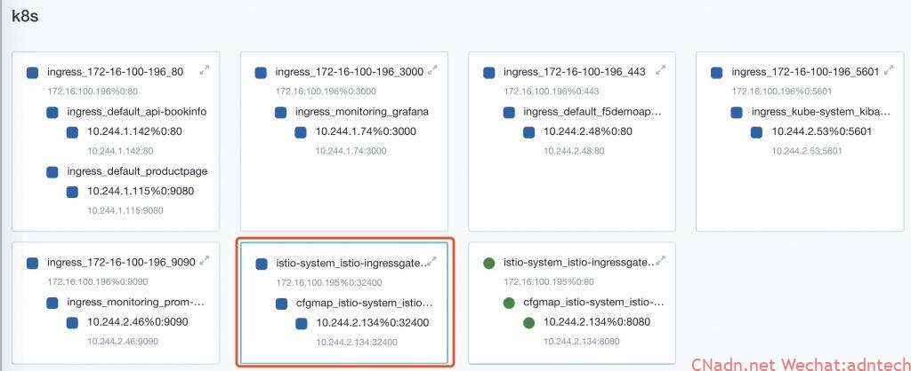
F5 will automatically generate the following configuration in the red box:
Simulate access to the business from the outside, you can see that it can be accessed normally
# jlin @ Mac in ~ [myf5.net]
$ for i in {1..2000}; do (date; sleep 1) | nc istiobookinfo.lab.f5se.io 32400; done
one Mon Jun 22 22:24:17 CST 2020
one Mon Jun 22 22:24:18 CST 2020
one Mon Jun 22 22:24:19 CST 2020
At this point, the newly released service monitor on Istio Ingressgateway is successfully automatically posted to BIGIP. Users only need to access BIGIP’s VS to access services within k8s (on Istio Ingressgateway).
For the subsequent release of other new port services, repeat the above steps.
Note: The above configuration uses the non-F5 AS3 configmap configuration method, if you are using CIS 2.0, you need to pay attention to this issue https://github.com/F5Networks/k8s-bigip-ctlr/issues/1341
Check more istio practice detail at my tech blog https://imesh.club